Adding stroke to 3D prisms in Manim
3 Nov 2021
Last updated
Table of Contents
- Disclaimers and clarifications
- Before and after
- The idea
- Problems with perspective
- Making a wireframe
Disclaimers and clarifications
Before diving deep into the code and specifics, I want to clarify some things. I am using ManimGL since it is what I’ve used to learn the basics of Manim, and the real-time rendering is very good for debugging and not creating new, unnecessary videos.
I know that ManimCE supports both real-time rendering and adding stroke to 3D Mobjects, but the already quite large codebase (5.1K lines at this point) made it very impractical to switch.
So I needed to create a new structure that allowed for adding strokes to 3D Mobjects, compatible with the already made animations and, obiously, parameterizable. Let’s go.
Before and after
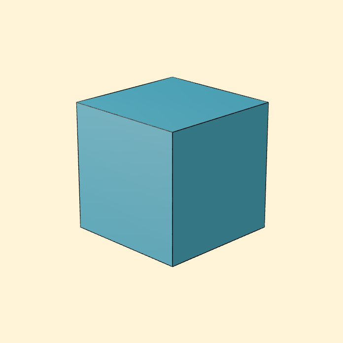
Here’s what we had at the beginning of the project:

and here’s how they’ll look afterwards.
The idea
The idea is that, when making the animation for Veritasium, I created the animation so the cubes sat down exactly next to each other, so they would basically blend together and look like a bigger shape rather than being able to identify each element.
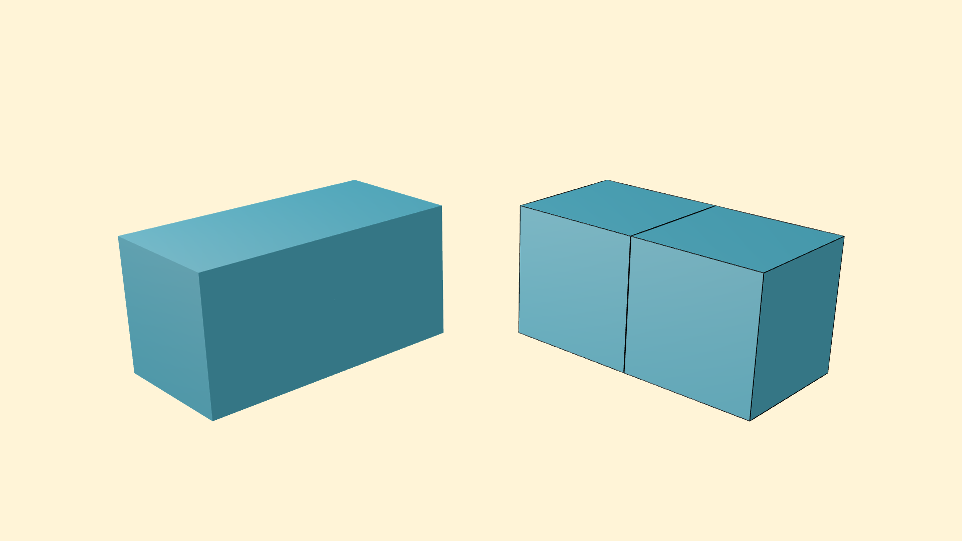
Adding a stroke (outline) to the shapes would very easily allow us to see where each shape starts and ends, and better keep track of the whole animation. Plus it just looks very stylish in my opinion.
Problems with perspective
Having clarified that I use ManimGL, by default, the 3D objects are created using shaders with openGL. This is very cool and convenient for lots of reasons, but there’s a problem.
The main class ManimGL refers to when creating 3D objects is Surface, and surfaces are made via UV methods and shaders. You cannot simply add a stroke to this.
That is why, lastly, I had an incredible idea: making a wireframe around the shape.
The idea is to simply create another shape with the same dimensions as the main one, but only with lines.
Line vs 3DLine
To do this, the first approach was to use Line. But you can see that this does not look very good.
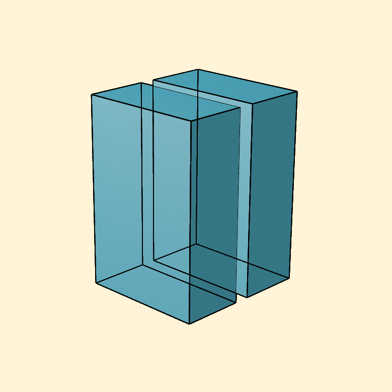
The problem we see here is that the renderer does not now how to calculate the interactions between 3D Mobjects and 2D Mobjects, that is, Cubes and Lines.
By calculate interactions I really mean, for example occlusion. That is, if a shape is sitting between another shape and the camera, you will only see part of the back-most shape, right?
Well, this does not apply with 2D objects, since they are not part of the 3D world of Manim somehow.
Luckily, there’s a 3DLine object in Manim, that addresses all the problems we had with the normal Line.
Making a wireframe
Now that’s good an all, but how do you make a wireframe for a cube?
Let’s compile some requirements:
- I want to develop a new class,
JPrism(J for Jesús, obviously), that works the exact same as a normalPrismbut has a stroke. - I want the stroke to be parameterizable. Not necessarily super easy but at least customizable.
- I want it to be properly rendered, so we’ll use
3DLine.
The algorithm
To create the edges of a cube, you can repeatedly and manually position some lines and such but that is lame. We are building an algorithm because we are fancy.
Thinking about the problem for a bit, we can reach some useful conclusions. Imagine that you have a unit cube with one of the vertices positioned right at the origin of our scene. The sides are length 1 in every direction, so it is a 1 tall-wide-deep cube.
Now think of the coordinates of the other vertices. The main one is in the origin, (0, 0, 0). But the other ones will be in a combination of (1, 0, 0), (1, 1, 0), (1, 0, 1)… and so on.
That looks a lot like binary numbers, and indeed, we can use this to our advantage.
We are going to create every possible combinations of 3D coordinates. We can very conveniently do this in python with the product function, which implements classic cartesian product for a set of things you pass into it. Cartesian product is a fancy way of saying “calculate every possible combination within this set of things”.
>>> vertices = list(product([0, 1], repeat=3))

output:
	[
		 (0, 0, 0),
		 (0, 0, 1),
		 (0, 1, 0),
		 (0, 1, 1),
		 (1, 0, 0),
		 (1, 0, 1),
		 (1, 1, 0),
		 (1, 1, 1)
	]
As we can see, we have every binary number from 0 to 7. That is 8 numbers, which coincides with the number of vertices in a cube. Cool!
Now, to construct a wireframe, we need to specify which two points to join together to form a line.
That is, we could make every possible combination of pairs of vertices, but that is not the wireframe we are looking for. That would look like this:
We need a way to filter the unnecessary edges. But how?
Well, thinking about it just a bit more, we can find a pattern. When you join any pair of vertices to form our little unit cube, we can see that in each pair, only one component of the coordinate changes.
That is, one valid edge would be from (0, 0, 0) to (0, 0, 1), or (0, 1, 0), but never from (0, 0, 0) to (1, 1, 0). Every pair of vertices whose coordinates change in more than one component would cross through some of the faces or inside the cube. And we want to filter these out.
But how? Let’s think a bit more!
XOR
If you recall, I mentioned something along the lines of “this looks like binary numbers”. Well, let’s go that way.
There’s a super cool, incredibly important operation in logic math called XOR. XOR takes two binary inputs and spits out a very interesting result. If they are equal, the output is 0, and 1 otherwise.
That means that the XOR tells us when two inputs are equal or not. See where we are going?
Making the XOR of two coordinates would look something like this:
(0, 0, 0)
(1, 0, 0)
_________ XOR
(1, 0, 0)


(0, 0, 0)
(1, 1, 0)
_________ XOR
(1, 1, 0)
The output will be another 3-coordinate tuple. What is the meaning of the result? Check this out: the sum literally indicates how many components have changed from one to another. Remember how many needed to change for our edge to be valid? One! Only one.
Filter
So now, we can use this to our advantage, specifying that we need every pair of coordinates whose xor operation yields a tuple whose sum is strictly less than 2. That was a mouthful.
We can write this in python using some functional programming like this:
every_edge = list(permutations(vertices, 2))

def filter_func(edge):
	return edge[0] != edge[1] and sum(xor(edge[0], edge[1])) < 2

filtered_edges = list(filter(filter_func, every_edge))
The result in filtered_edges looks something like:
[
	 ((0, 0, 0), (0, 0, 1)),
	 ((0, 0, 0), (0, 1, 0)),
	 ((0, 0, 0), (1, 0, 0)),
	 ((0, 0, 1), (0, 0, 0)),
	 ((0, 0, 1), (0, 1, 1)),
	 ((0, 0, 1), (1, 0, 1)),
	 ((0, 1, 0), (0, 0, 0)),
	 ((0, 1, 0), (0, 1, 1)),
	 ((0, 1, 0), (1, 1, 0)),
	 ((0, 1, 1), (0, 0, 1)),
	 ((0, 1, 1), (0, 1, 0)),
	 ((0, 1, 1), (1, 1, 1)),
	 ((1, 0, 0), (0, 0, 0)),
	 ((1, 0, 0), (1, 0, 1)),
	 ((1, 0, 0), (1, 1, 0)),
	 ((1, 0, 1), (0, 0, 1)),
	 ((1, 0, 1), (1, 0, 0)),
	 ((1, 0, 1), (1, 1, 1)),
	 ((1, 1, 0), (0, 1, 0)),
	 ((1, 1, 0), (1, 0, 0)),
	 ((1, 1, 0), (1, 1, 1)),
	 ((1, 1, 1), (0, 1, 1)),
	 ((1, 1, 1), (1, 0, 1)),
	 ((1, 1, 1), (1, 1, 0))
 ]
And our wireframe looks like this!
Since the lines are also objects, those can be parameterizable, so that’s also cool. And I built a class that I could simply replace into the original animation, and everything worked flawlessly, but now with outlined cubes!
I find this to be probably overkill, but I’ve learned lots of things along the way and forced myself to think a bit more outside the box. (pun intended)
That’s it. Here’s some dancing cubes for you.